AC/DC DRIVES
AC DRIVES
Sales & Services by BGS Group, it’s a famous brand all kind of VFD SERVICING . It’s mainly used to control and adjust three phase AC motor’s speed. Due to its stable performance, rich combination of features, high performance vector control technology, low speed with high torque output, good dynamic characteristics and superior overload capacity, BGS groups occupy an important position in global VFD markets.
VFDs are used to control AC induction motor speed and torque, while the induction motor is the major equipment in industrial areas. BGS is the global market leader of variable frequency controller and motor areas.
Variable frequency technology extends the motor running speed range – from zero speed to above the motor rated speed – to improve the production efficiency of the transmission process significantly. In the case the motor only needs a lower capacity, the VFD can reduce the motor speed to save energy.
ABB standard drives are easy to installation, set up and operation, to save a lot of time for you. The VFDs are widely available and thus it called standard drives. Those drives have common field bus interface, processes, specifications, design, debug and maintenance.
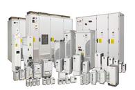
ABB ACS 2000 DRIVES
ABB Air-cooled ACS 2000 VFD drive is dedicated to the cement, mining, metallurgy, pulp and paper, water supply, electricity and chemical, oil gas etc, for the fans, pumps , compressors , and other common applications.
ABB ACS 2000 drives combine with innovative technology to address the industry challenges , such as the flexible power supply connections, lower harmonics, reduce energy consumption, SVC (Static Var Compensator) and easy installation, debugging.
Flexible Power Supply Connection
VFD drives can be without using the input isolation transformer, depending on user’s choice and the existing equipment situation, thus allow the variable frequency drive connects to the power supply directly (direct power grid connection), or can be connected to a input isolation transformer.
In direct power grid connection configuration mode, clients can benefit from the lower investment cost due to there is no transformer. Compare with other VFDs which need transformer, ABB ACS 2000 drives have more compact design, lighter weight, lower transportation costs, and need smaller installation space.
Lower Harmonics
ABB ACS 2000 drives integrated Active Front End (AFE) technology, without using expensive and dedicated transformer, ACS2000 VFD can minimize the power grid harmonic, and with additional four-quadrant operation and reactive power compensation benefits.
AFE provides low harmonic to meet the various criteria for current and voltage harmonics requirements. Thus, there is no need for harmonic analysis or installing a line filter.
Reduce Energy Consumption
In order to achieve minimize energy consumption, AFE allows four-quadrant operation to make braking energy back to the power grid.
Reactive Power Compensation
AFE also can provide reactive power compensation. With SVC, the VFD can maintain a smooth voltage characteristic, and avoid the reactive power punishment.
Easy Installation, Commissioning And Maintenance
With direct power supply connection technique, to allow the VFD installation and commissioning work faster and more convenient. Installing a VFD, simply use ABB “three in – three out” wiring concept, disconnect the direct power supply running and connect to the VFD, then connect the VFD to the AC motor.
ABB ACS2000 drives were designed with withdrawable phase module for quick replacing all of the VFD’s components from the drive’s front side, the mean time to repair (MTTR) is in leading level of the whole industry.
High Reliability
ABB ACS 2000 drives adopt multi-level voltage source inverter (VSI) topological structure, mature high voltage IGBT power semiconductor technology and Direct Torque Control (DTC) motor control platform. Therefore, ACS2000 VFDs have high reliability, extend the mean time between failures (MTBF) and increased utilization.
ABB ACS 2000 VFD inherited the VSI topological structure and uses a patented IGBT-based multi-level design, provides near-sinusoidal current and voltage waveforms, makes the VFD compatible with standard motor and cable.
ACS 2000 VFD’s control platform uses ABB’s award-winning DTC platform, which provides maximum torque, speed performance and lowest energy loss which never happened in medium voltage variable frequency drives. In all conditions, the VFD’s control is quick and smooth.
Lower Investment Cost
Flexible power supply connection, lower harmonics and power consumption, easy installation and commissioning reliability to make ABB ACS 2000 drives have a low total investment cost throughout it’s service life cycle.
ABB ACS 510 DRIVES
ACS510 VFD is ABB’s another outstanding low voltage AC drive. ACS510 VFD has easy installation, configuration and operation to save a significant time.
Application
ABB drives are used in industrial areas, ACS510 VFDs are especially for fan and water pump drive, the typical applications include constant pressure water supply, cooling fan, subway, tunnel fan and so on.
ABB ACS 510 Drives Highlights
- Perfect match with fan and pump applications
- Advanced control panel
- Patented technology to reduce harmonics, swinging choke
- Loop soft start
- Multi-point V/F curve
- Built-in RFI filters as standard
- CE certification
ABB ACS 510 drives Key Features
- Perfect match with fan pump.
- Enhanced PFC application: Control up to 7 (1+6) pumps, it’s able to switch more pumps.
- SPFC: loop soft start function, each pump can be adjusted in turn.
- Multi-point V/F curve: freely definable 5 V/F curves for flexible applications.
- PID regulator: Built-in two separate PID controller, PID1 can set two parameters, PID2 can control an independent external valves.
More Economic
Intuitive features: noise optimization, when the drive temperature reduced, increase the switching frequency, control cooling fan starts only when needed, can be distributed switching frequency randomly, thus reducing noise, improving the motor noise greatly and improve effect.
Magnetic flux optimization: reduce the motor magnetic flux automatically when the loads decrease, and reduce energy consumption and noise significantly.
Connection: easy wiring, simple install, and can be installed side by side.
More environmentally friendly.
EMC: For the first and second environment RFI filters as standard VFDs, without using additional external filters.
Reactor: swinging chokes, match inductance depending on different loads, thus suppressing and reducing harmonics and reduce total harmonic.
ABB ACS140 DRIVES
For 0.12-2.2KW squirrel-cage motor’s speed and torque control.
As one of Comp-AC family, ACS140 enriched ABB drives. Despite its small size, it contains a number of high-performance transmission’s features. It is very suitable for gases, liquids, solids handling processes, typical applications include: packaging machines, washing machines, blender, conveyors, pumps and so on.
ABB ACS140 drives have maximum design reliability. OEM distributors can choose cooling mode freely. For flange-mounted, the module generated heat will be dissipated outside the enclosure directly. To further enhance the drives reliability, the number of module’s components has been minimized as much as possible.
ABB ACS140 drives output frequency is sensitivity to follow the given signal changes. The average accuracy is better than 1%, fast response, with an average delay time of less than 9 mm.
ABB ACS140 DRIVES FEATURES
Small size, light weight, easy to install and use, suitable for 0.12-2.2KW ordinary squirrel cage motor’s speed control.
Convenient installation: DIN rail mounting, flange-mounting and wall-mounting.
Stable speed adjusting performance, strong overload capacity, low-speed with high torque output. Install additional input filters can reduce the pollution to the power grid.
ABB ACS400 DRIVES
Power range 2.2-37KW.
Flexible modular design and minimal number of components.
DC voltage automatic regulate, a variety of communication functions.
ABB ACS400 VFDs are in 2.2-37KW power range, the maximum benefits are energy conservation, accurate control, safe and reliable, use aluminum and plastic parts to ensure the VFD sufficient precision, ACS400 VFDs main power supply is 230-500V 50/60Hz, control power is 115-230V. Adopt the latest IGBT technology in excitation, the magnetic field voltage does need to match the transformer, magnetic field line fuses and reactors have also been integrated in ABB DCS400 module. As the magnetic field using the three-phase line supply, and get power from the three-phase power supply directly, thus DCS400 VFD does not need a separate field power line. ABB DCS400 drive has a variety of debugging tools. Setup parameters under the guidance of the Commissioning Wizard, plus with self-optimization debugging process, DCS400 VFD’s typical debugging time is 15 minutes.
ABB ACS550 DRIVES
Assistant Control Panel, 11KW VFD and blow power drives built-in brake chopper as standard.
Sensorless vector control.
Start wizard – guides the user to set parameters without entering to the drive’s parameter list.
Diagnostic wizard – active in fault situation, which will help to find the VFD’s faults quickly.
Maintenance wizard – monitor running hours or motor rotation.
ABB ACS150 DRIVES
Applications: fans, pumps, gated, material handling, conveyor.
ACS150 VFD Highlights:
FlashDrop – transmission setting and speed adjusting is more quickly and easily, can be used for volume manufacturing.
Fixed control panel – comfortable and durable interface transmission.
Fixed Potentiometer – intuitive speed setting.
Integrated EMC filter – no need external filters.
Built-in brake chopper – reduce costs, save space and simplify wiring.
Flexible installation – optimized layout and efficient cabinet space utilization.
Layers of circuit boards – longer life and reduce maintenance.
ABB ACS 510 Drives Highlights
- Perfect match with fan and pump applications
- Advanced control panel
- Patented technology to reduce harmonics, swinging choke
- Loop soft start
- Multi-point V/F curve
- Built-in RFI filters as standard
- CE certification
ABB ACS 510 drives Key Features
- Perfect match with fan pump.
- Enhanced PFC application: Control up to 7 (1+6) pumps, it’s able to switch more pumps.
- SPFC: loop soft start function, each pump can be adjusted in turn.
- Multi-point V/F curve: freely definable 5 V/F curves for flexible applications.
- PID regulator: Built-in two separate PID controller, PID1 can set two parameters, PID2 can control an independent external valves.
ABB ACS350 DRIVES
Meet the needs of a wide range of machinery applications, such as food & beverage, material handling, textile, printing, rubber & plastics, and woodworking machinery etc.
ACS350 VFD Highlights
FlashDrop – transmission settings and speed adjustment are more quickly and easily, can be used for bulk manufacturing.
Sequence programming – standard logic programming, decrease the requirements of external PLC.
Software – high-tech, high performance, high flexibility.
User Interface – without control panels to save costs, but also provide different control panels
according to functional needs.
Cabinet Compatibility – Optimum installation layout.
Built-in EMC – no extra space, parts, time or cost.
Transmission protection – protect the transmission with the best quality latest solution.
ABB ACS800 DRIVES
The biggest advantage of ABB ACS800 VFD is using the same control technology in the whole power range drives, such as starting wizard, custom program, DTC control, common parts, common interface technology, and the common software tools for the VFD selection, commissioning and maintenance.
Newest Technology
The core technology of ABB ACS800 VFD is direct torque control (DTC), which is the most advanced AC induction motor control method currently. The outstanding performance and stability of DTC make the ACS800 drives are suitable for a variety of industrial fields.
Startup Wizard
ABB drives are continuous improvement in user interface. Startup Wizard makes ACS800 VFD debugging becomes very easy.
Custom Programming
Compare with traditional parametric programming, ABB ACS800 VFD’s custom programming has better adaptability. As a standard configuration of all range drives, it’s like the drive built-in a small PLC, and do not need to add any additional hardware and software.
Highly Integrated And Compact Design
As standard component, ABB ACS800 VFD has built-in reactor. In addition, you can install additional three modules in ABB ACS800 VFD: I/O extension modules, fieldbus adapter module, pulse encoder interface module or PC interface module. For these modules, no need additional space and cable.
Environmentally Friendly
ABB is the business member of ICC (International Chamber of Commerce) sustainable development, ABB drives follow the 16 provisions of the ICC, and follow the ISO14001 standard in the production process.
ABB ACS1000 DRIVES
ACS1000 high voltage VFD is for 310-5000KW motors speed and torque control, voltage rating of 2.3, 3.3 and 4.16kV, this drive has excellent speed and torque control characteristics.
Smooth System Integration
ABB ACS1000 VFDs have a variety of flexible combination options to suit a variety of new or renovation projects with different requirements. Minimize interference to the existing equipment and power grid.
Superb Performance
Using ABB’s patented DTC (Direct Torque Control) technology, ACS1000 series VFD provides precise process control, DTC can provide the most rapid response for any motor torque control platform. Without using encoder, it can guarantee the best control precision even if the input power changes and load sudden changes.
AC DRIVE VERSUS SOFT STARTER
A Soft Starter is just that. It allows the motor to ramp up to full speed and maybe ramp down to a stop. An AC drive is needed to control speed and usually includes additional features such as multiple speed settings and S curve deceleration. Consider the needs of your application and the benefits of additional flexibility versus the difference in cost. For smaller motors, an AC drive will often provide a lot of additional flexibility and future proofing for a small additional cost. But, this is not always the case so it really depends on the details of you application and budget.
A soft starter is a starter configured such that it will ramp up the voltage/current allowing the motor to start off slowly and pick up speed without the typical in rush.
The AC drive is as variable frequency drive which allows the motor to be operated over a range of speed in a controlled manner, and since you can control the speed of the motor it could have the effect of a Soft Starter.
AC drive is obviously more costly, it can have two acceleration sessions with different ramping rates (from still to minimum speed with and from min speed to target speed), some delay is added prior to start.
Soft Starter is like a 2 stage starter like half voltage when a pump starts rolling a timer runs down then full voltage full speed, AC drive as is description variable voltage has capacitors to vary the voltages.
If an application and say pump at full volume is required then you can go with a Soft Starter (also reduces line voltage inrush current demand when starting), If application requires you to control and able to adjust for a volume demand then go with an AC drive.
“But” you can operate an AC drive at a fixed speed and have the ability control the startup ramp rate and also ramp rate as it shuts down, I haven’t had any soft starters ramp a motor down in reverse order as startup just cuts off the voltage when shutting down.
VFD IN CRANE AND HOIST APPLICATIONS
None of the overhead hoist and crane manufacturers, service and sales companies, out of the more than 1,500 we deal with directly, are using other than asynchronous motors. When we discuss the 90% efficiency achievable via the use of variable frequency drives (VFD), it’s not optimistic, it’s factual. Is it always the case? Maybe not, but in reality these efficiency figures have reached 94%.
HOIST
As regards the continuing usage of asynchronous motors in Overhead Hoist and Crane applications, if there is a manufacturer using anything other than that, with the exception of consequential pole motors, I am in touch with many and as yet that roster remains, to the most current information I have available, empty.
With regards to encoder usage in hoisting applications, sensorless vector is indeed in use by manufacturers in the US and abroad, and though I’m not entirely sold on that as yet, it seems to be working. Time will tell, but so far, I’m not aware of attributable accident reports. But, asynchronous motors are convenient for all overhead crane motions, without limitations as to traversal or hoisting applications. I’m not as yet certain, either, that the research and testing it would take to prove the motors you propose are indeed universally applicable, would reach the market with competitive pricing to asynchronous units in any sense of an immediate future. There would have to be a viable incentive in all factors to be considered, that hasn’t as yet arisen.
I really doubt the overhead crane industry would turn a blind eye to a better motor, but you must consider the reality of the applications regarding the receptiveness of the equipment buyers. They are the ones with the sign over their doors, and with the liability of injury risks and/or equipment damage potential, there is an understandable reluctance to try other than the proven.
Personally, when I introduced the VFDs I am using into the overhead crane industry, though the manufacturer of them is well known worldwide and very favorable, nobody in the OHC industry in the US had heard of them. It took me literally nearly 9 years to gain acceptability before gaining universal acceptance and the question from the potential end user was always the same: “Who else has used these for years without problems?” That had to be answered with references, and until it was, it was a one at a time proving ground effort. While I can’t disagree with any potential component improvement efforts and the benefits they may bring, two factors remain in place. One is the component cost. The other is the end user attitudes that basically amounts to a ‘Go fight city hall’ change prospective for acceptance.
VFD FOR FANS & PUMPS
As regards the continuing usage of asynchronous motors in Overhead Hoist and Crane applications, if there is a manufacturer using anything other than that, with the exception of consequential pole motors, I am in touch with many and as yet that roster remains, to the most current information I have available, empty.
With regards to encoder usage in hoisting applications, sensorless vector is indeed in use by manufacturers in the US and abroad, and though I’m not entirely sold on that as yet, it seems to be working. Time will tell, but so far, I’m not aware of attributable accident reports. But, asynchronous motors are convenient for all overhead crane motions, without limitations as to traversal or hoisting applications. I’m not as yet certain, either, that the research and testing it would take to prove the motors you propose are indeed universally applicable, would reach the market with competitive pricing to asynchronous units in any sense of an immediate future. There would have to be a viable incentive in all factors to be considered, that hasn’t as yet arisen.
I really doubt the overhead crane industry would turn a blind eye to a better motor, but you must consider the reality of the applications regarding the receptiveness of the equipment buyers. They are the ones with the sign over their doors, and with the liability of injury risks and/or equipment damage potential, there is an understandable reluctance to try other than the proven.
Personally, when I introduced the VFDs I am using into the overhead crane industry, though the manufacturer of them is well known worldwide and very favorable, nobody in the OHC industry in the US had heard of them. It took me literally nearly 9 years to gain acceptability before gaining universal acceptance and the question from the potential end user was always the same: “Who else has used these for years without problems?” That had to be answered with references, and until it was, it was a one at a time proving ground effort. While I can’t disagree with any potential component improvement efforts and the benefits they may bring, two factors remain in place. One is the component cost. The other is the end user attitudes that basically amounts to a ‘Go fight city hall’ change prospective for acceptance.
Benefits of VFDs In Fans & Pumps Applications
Most fans and water pumps are selected according to its full loads working status, but in practice they are not working at the full load state in most of the time. So to control flow & air volume of the pumps & fans, it needs a wind deflector, reflux valve or start/stop timer usually, and the large power ac motors are very difficult in start/stop frequently as the electric impact is in a high level, during this time, it’s absolutely will cause electric energy wasted and high current impact during start/stop of the ac motor.
To solve this kind of problem, the most scientific way is to adopt a variable frequency drive to control the fans and water pumps. When the AC motor operates at 80% of its rated rotation speed, in theory, the power consumption is the cube of 80% of its rated power, i.e. 51.2%. Generally, it can almost save 40% power consumption for the manufacturer when deduct the impact of mechanical loss and ac motor copper and iron loss. Plus, it can improve energy-efficient when the fan & pump adopt closed-loop constant-pressure control which can be achieved easily. Due to the VFD drive can realize soft start and soft stop for the ac motors, it can avoid voltage surge during the motor’s start period to decrease the failure rate and increase its service life, and reduce the power system’s capacity requirements and reactive power loss.
Energy Conservation Analysis
Through the fluid mechanics’ basic principles, we know the fans and pumps are belong to square torque loads, the rotation speed n, flow Q, pressure H and shaft power P relation: Q∝n, H∝n2, P∝n3, i.e., the flow is in proportion to its rotation speed, the pressure is in proportion to the square of its rotation speed, and the shaft power is in proportion to the cube of its rotation speed.
We now take the fan as an instance of the principle in energy conservation. As show in following fig, when the fan in its rated rotation speed, the air volume and air pressure change as curve 1, which intersects with the pipe network resistance curve 2 at the rated working condition point N when the air door is full opened; the air volume of the fan is Qn and the pressure is Hn. Normally, the working condition point is moved to point E by closing the regulation air door and increasing the resistance in ventilation pipe network. At this moment, the air volume is decreased to Qe and the generated pressure head is He. If the air volume is regulated by reducing the rotation speed of the fan, the fan will operate as curve 4, and re-generate required air volume Qe, it will intersect with the pipe network resistance curve 2 at the working condition point C when the air door is full opened.
VFD In Fans And Pumps
According to the similar principles between fan and water pump, the air volume, rotation speed and power accordance with the following formula:
Fan And Pump Formula
According to similar principles, when the rotation speed of the fan reduce to n2 from n1, the shaft power of the fan N2 will be reduced to N1 multiply (n1/n2)3; the shaded area in the FIG – the area covered by JECF represents the saved electric quantity by reducing rotation speed compared with closing the air door to regulate the same amount of air volume. Both theory and actual measurement prove that it will cause waste of electric energy by manual increasing ventilation resistance (closing the valve) to regulate the air volume, which is unacceptable.
If variable frequency technology is adopted to change the rotation speed of pumps and fans to control other process control parameters on the field such as pressure, temperature and water level, the comparison results mentioned above can also be obtained by drawing the relation curve in accordance with the system control characteristics. In other words, the method to adopt VFD to change the rotation speed of ac motor is more energy and cost efficient than by using valve and damper, and the operating condition of the equipment is also significantly improved.
Variable Frequency Reform Solution
Keep the original system but add the variable frequency drive part, All motors in the system are driven by corresponding VFDs, and when the VFD failed, the system can working in power frequency as the original control system to ensure continuous production in the factory.
Control Circuit
A. Manual regulate (open-loop regulation) system, adjust output frequency of the VFD in manual control mode to change the rotation speed of the fan & pump to regulate air volume & water volume. It’s same as original method of regulating the air door (gate valve).
B. Automatic regulate (closed-loop regulation) system:
VFD automatic regulate system. The automatic control system adopts closed-loop regulation which is consisted of the VFD’s built-in PID function with external pressure sensor or pressure gage. The sensor detects air pressure or water pressure in real time and transforms it into 4-20mA current signal (or 0-10V voltage signal), and sends it to the PID regulator, and through internal calculation of the variable speed drive, automatic regulate the frequency of the VFD to stabilize the air volume or water pressure at the set value.
Main features of vector control VFD in Fan and Water Pump application
The VFD is a product special designed for load with square torque like in fan and water pump applications, cost effective and reliable, it’s an ideal choice for your energy saving system.
Wide range operation voltage, fluctuation range in 304 – 456V AC.
Special rotation speed tracking technology with no impact.
Several V/F curves in setting.
Multi-function input/output terminals with Multi-path definable function.
Re-start function in instant power off.
Built-in RS 485, support MODBUS-RTU communication protocol.
Stable start, suitable for high-inertia load’s speed regulation.
Easy to realize closed-loop automatic operation with advanced built-in PID algorithm.
System Characteristics After Reform
- Realize AC motor’s soft start/stop by adopting VFD control, to increase the equipment’s service life and avoid impact on the power system.
- Control the AC motor’s rotation speed by the variable speed drive, remove the damper adjustment to decrease failure rate of the application, and increase electricity saving significantly.
- The ac motor operates below rated rotation speed, to decrease impact of noises to the environment.
- Do not affect original power facilities & environment during installation to allow continuous production.
- Enhance overload, overvoltage, overcurrent, undervoltage and voltage phase lack protection functions, and audible and visual alarm function.
- Due to keep the original system wiring and make the system have two working modes in normal power frequency & variable frequency power, the whole system operate in a more reliable situation.
Can I control multiple motors on one VFD
Multiple motors operation is quite common application. There are many applications like textile, printing etc where multi motor operation is very common. I have seen many VFD manufacturers recommending multiple motor operation. Say in a textile loom, there could be scores of Motors running spinning pumps, godets, winders etc. If there are some 40 Motors of say 0.5 HP, then one can certainly go in for one single variable frequency drive of say 25 hp rating. That would be the best and most economical and practical solution.
But, certain conditions, considerations and safety must be met. First each motor must be individually protected, consider the load, speed, torque, etc on EACH motor. Now this is tricky if the gearboxes are used. You have to consider are they new? Are they used and if so how much “SLACK” does each have as all these things play into the “LOAD” of each individual motor amp draw! Also, I would use 2 OL on each 3 phase load on the load side. Most of the time the cost of the motor is miniscual compared to the VFD. So protect it at all cost. Here’s a novel idea, “Ask the Manufacturer”! Not being a smarty pants, just want my fellow peer to do as good a job as he or she can and sometimes that means reading the instructions. Hope all this helps and if you will let me know the layout and how it works out for you.
VFD reactor
Quality VFD’s incorporate either an AC Reactor or DC Reactor (choke). Their inclusion in the basic design of the VFD allows the design engineer to maximize the advantages of the choke. Their function is to reduce the current distortion caused by the input stage rectifiers by slowing the rate of change of current, and thus charging the internal capacitor at a slower rate over a longer time.
Some VFD’s allow aftermarket fitment of DC chokes but access to the DC bus is required. While it is easy to add AC chokes to the input stage, there is a disadvantage of voltage drop to the VFD that may have to be considered.
The Harmonic Distortion caused by a VFD is related to its size & load, choke size, and the supply network parameters.
With no AC Reactor or DC Choke, the harmonic distortion will be greater.
Another consideration should be a properly sized source transformer that provides enough impedance. The sized source transformer used as an isolation transformer (although a bit more of an investment) should provide 3 to 5% impedance yet also provides Voltage Transient mitigation with ten to one reduction in impulse peaks, as well as noise reduction through the use of a Delta primary to Wye secondary with center tap ground. As Joe above states it provides additional protection for the VFD drives front (Converter) end while proper ground of the Source to Drive, Drive to Motor and Motor to Voltage Source assists in mitigating high frequency noise, especially when flat braid is used as the grounding straps. This protects your investment and assists in keeping the VFD’s from generating noise into the supply that can compromise your nearby instrumentation, and PLC power supplies, etc. As well you can tap up the transformer giving you a higher input voltage mitigating the voltage drop issues resulting from the higher impedance.
The DC link assists in mitigating DC Bus Ripple and increasing the input impedance enabling a slower inrush for power on and sudden demand current requirements furthering the life of your capacitors, while a sized supply transformer protects the front end of the drive by providing voltage noise protection and adding input impedance for smoother current and adding a capability to change taps to prevent a voltage drop, while input reactors slow inrush current furthering the life of your input components and capacitors but add no protection from Voltage impulses or noise to the variable frequency drive converter components, and add voltage drop increasing stress on those components. The important thing to remember is that “Proper” systemic design protects your drive(s) and system components investment.
VARIABLE FREQUENCY DRIVE PREVENTIVE MAINTENANCE
Preventive Maintenance is all great for the variable frequency drive, cleaning with dry air, checking connections and tightening with correct torque wench/driver, replacing fan and having spare. To avoid fault during operation it is always better to perform preventive maintenance of variable frequency drive as per manufacturer recommendations. Certainly dust, moisture and loose connections are main causes of fault. Only rotating part is fan so should be check noise of fan. Clean and dry air is required to clean the variable frequency drive. Connections should be tighten with recommended torque with torque wrench.
Replacing capacitor due to age should be done only in a repair shop that can load test the VFD drive after replacement. Remember for most spare drives have been on the shelf for over a year you need to reform the capacitors as part of the yearly maintenance. Also remember that if the system is not checked like the motor cable/connections, belts and couplings the variable frequency drive can still be damaged. Yearly preventive maintenance is always for the system not the VFD self in my opinion.
Benefits of VFDs In Fans & Pumps Applications
Most fans and water pumps are selected according to its full loads working status, but in practice they are not working at the full load state in most of the time. So to control flow & air volume of the pumps & fans, it needs a wind deflector, reflux valve or start/stop timer usually, and the large power ac motors are very difficult in start/stop frequently as the electric impact is in a high level, during this time, it’s absolutely will cause electric energy wasted and high current impact during start/stop of the ac motor.
To solve this kind of problem, the most scientific way is to adopt a variable frequency drive to control the fans and water pumps. When the AC motor operates at 80% of its rated rotation speed, in theory, the power consumption is the cube of 80% of its rated power, i.e. 51.2%. Generally, it can almost save 40% power consumption for the manufacturer when deduct the impact of mechanical loss and ac motor copper and iron loss. Plus, it can improve energy-efficient when the fan & pump adopt closed-loop constant-pressure control which can be achieved easily. Due to the VFD drive can realize soft start and soft stop for the ac motors, it can avoid voltage surge during the motor’s start period to decrease the failure rate and increase its service life, and reduce the power system’s capacity requirements and reactive power loss.
Energy Conservation Analysis
Through the fluid mechanics’ basic principles, we know the fans and pumps are belong to square torque loads, the rotation speed n, flow Q, pressure H and shaft power P relation: Q∝n, H∝n2, P∝n3, i.e., the flow is in proportion to its rotation speed, the pressure is in proportion to the square of its rotation speed, and the shaft power is in proportion to the cube of its rotation speed.
We now take the fan as an instance of the principle in energy conservation. As show in following fig, when the fan in its rated rotation speed, the air volume and air pressure change as curve 1, which intersects with the pipe network resistance curve 2 at the rated working condition point N when the air door is full opened; the air volume of the fan is Qn and the pressure is Hn. Normally, the working condition point is moved to point E by closing the regulation air door and increasing the resistance in ventilation pipe network. At this moment, the air volume is decreased to Qe and the generated pressure head is He. If the air volume is regulated by reducing the rotation speed of the fan, the fan will operate as curve 4, and re-generate required air volume Qe, it will intersect with the pipe network resistance curve 2 at the working condition point C when the air door is full opened.
VFD In Fans And Pumps
According to the similar principles between fan and water pump, the air volume, rotation speed and power accordance with the following formula:
Fan And Pump Formula
According to similar principles, when the rotation speed of the fan reduce to n2 from n1, the shaft power of the fan N2 will be reduced to N1 multiply (n1/n2)3; the shaded area in the FIG – the area covered by JECF represents the saved electric quantity by reducing rotation speed compared with closing the air door to regulate the same amount of air volume. Both theory and actual measurement prove that it will cause waste of electric energy by manual increasing ventilation resistance (closing the valve) to regulate the air volume, which is unacceptable.
If variable frequency technology is adopted to change the rotation speed of pumps and fans to control other process control parameters on the field such as pressure, temperature and water level, the comparison results mentioned above can also be obtained by drawing the relation curve in accordance with the system control characteristics. In other words, the method to adopt VFD to change the rotation speed of ac motor is more energy and cost efficient than by using valve and damper, and the operating condition of the equipment is also significantly improved.
Variable Frequency Reform Solution
Keep the original system but add the variable frequency drive part, All motors in the system are driven by corresponding VFDs, and when the VFD failed, the system can working in power frequency as the original control system to ensure continuous production in the factory.
Control Circuit
A. Manual regulate (open-loop regulation) system, adjust output frequency of the VFD in manual control mode to change the rotation speed of the fan & pump to regulate air volume & water volume. It’s same as original method of regulating the air door (gate valve).
B. Automatic regulate (closed-loop regulation) system:
VFD automatic regulate system. The automatic control system adopts closed-loop regulation which is consisted of the VFD’s built-in PID function with external pressure sensor or pressure gage. The sensor detects air pressure or water pressure in real time and transforms it into 4-20mA current signal (or 0-10V voltage signal), and sends it to the PID regulator, and through internal calculation of the variable speed drive, automatic regulate the frequency of the VFD to stabilize the air volume or water pressure at the set value.
Main features of vector control VFD in Fan and Water Pump application
The VFD is a product special designed for load with square torque like in fan and water pump applications, cost effective and reliable, it’s an ideal choice for your energy saving system.
Wide range operation voltage, fluctuation range in 304 – 456V AC.
Special rotation speed tracking technology with no impact.
Several V/F curves in setting.
Multi-function input/output terminals with Multi-path definable function.
Re-start function in instant power off.
Built-in RS 485, support MODBUS-RTU communication protocol.
Stable start, suitable for high-inertia load’s speed regulation.
Easy to realize closed-loop automatic operation with advanced built-in PID algorithm.
System Characteristics After Reform
- Realize AC motor’s soft start/stop by adopting VFD control, to increase the equipment’s service life and avoid impact on the power system.
- Control the AC motor’s rotation speed by the variable speed drive, remove the damper adjustment to decrease failure rate of the application, and increase electricity saving significantly.
- The ac motor operates below rated rotation speed, to decrease impact of noises to the environment.
- Do not affect original power facilities & environment during installation to allow continuous production.
- Enhance overload, overvoltage, overcurrent, undervoltage and voltage phase lack protection functions, and audible and visual alarm function.
- Due to keep the original system wiring and make the system have two working modes in normal power frequency & variable frequency power, the whole system operate in a more reliable situation.
Can I control multiple motors on one VFD
Multiple motors operation is quite common application. There are many applications like textile, printing etc where multi motor operation is very common. I have seen many VFD manufacturers recommending multiple motor operation. Say in a textile loom, there could be scores of Motors running spinning pumps, godets, winders etc. If there are some 40 Motors of say 0.5 HP, then one can certainly go in for one single variable frequency drive of say 25 hp rating. That would be the best and most economical and practical solution.
But, certain conditions, considerations and safety must be met. First each motor must be individually protected, consider the load, speed, torque, etc on EACH motor. Now this is tricky if the gearboxes are used. You have to consider are they new? Are they used and if so how much “SLACK” does each have as all these things play into the “LOAD” of each individual motor amp draw! Also, I would use 2 OL on each 3 phase load on the load side. Most of the time the cost of the motor is miniscual compared to the VFD. So protect it at all cost. Here’s a novel idea, “Ask the Manufacturer”! Not being a smarty pants, just want my fellow peer to do as good a job as he or she can and sometimes that means reading the instructions. Hope all this helps and if you will let me know the layout and how it works out for you.
VFD reactor
Quality VFD’s incorporate either an AC Reactor or DC Reactor (choke). Their inclusion in the basic design of the VFD allows the design engineer to maximize the advantages of the choke. Their function is to reduce the current distortion caused by the input stage rectifiers by slowing the rate of change of current, and thus charging the internal capacitor at a slower rate over a longer time.
Some VFD’s allow aftermarket fitment of DC chokes but access to the DC bus is required. While it is easy to add AC chokes to the input stage, there is a disadvantage of voltage drop to the VFD that may have to be considered.
The Harmonic Distortion caused by a VFD is related to its size & load, choke size, and the supply network parameters.
With no AC Reactor or DC Choke, the harmonic distortion will be greater.
Another consideration should be a properly sized source transformer that provides enough impedance. The sized source transformer used as an isolation transformer (although a bit more of an investment) should provide 3 to 5% impedance yet also provides Voltage Transient mitigation with ten to one reduction in impulse peaks, as well as noise reduction through the use of a Delta primary to Wye secondary with center tap ground. As Joe above states it provides additional protection for the VFD drives front (Converter) end while proper ground of the Source to Drive, Drive to Motor and Motor to Voltage Source assists in mitigating high frequency noise, especially when flat braid is used as the grounding straps. This protects your investment and assists in keeping the VFD’s from generating noise into the supply that can compromise your nearby instrumentation, and PLC power supplies, etc. As well you can tap up the transformer giving you a higher input voltage mitigating the voltage drop issues resulting from the higher impedance.
The DC link assists in mitigating DC Bus Ripple and increasing the input impedance enabling a slower inrush for power on and sudden demand current requirements furthering the life of your capacitors, while a sized supply transformer protects the front end of the drive by providing voltage noise protection and adding input impedance for smoother current and adding a capability to change taps to prevent a voltage drop, while input reactors slow inrush current furthering the life of your input components and capacitors but add no protection from Voltage impulses or noise to the variable frequency drive converter components, and add voltage drop increasing stress on those components. The important thing to remember is that “Proper” systemic design protects your drive(s) and system components investment.
DC DRIVES
With DC drives from BGS you can significantly reduce drive, cost, converter families deliver top performance and integrated intelligence for maximum availability. Perfectly aligned to our DC motors, our DC drives offer maximum availability and user friendliness.
Highly innovative bidirectional DC-DC converter and completes our offering for grid applications. It suits perfectly for industrial as well as for multi-generator applications.
Excitation system is suitable from low to high power classes, mainly in hydroelectric, gas and steam power plants and set itself apart with the high level of reliability and efficiency.
SINAMICS DCM DC Converter, the chassis unit that can be universally used
SINAMICS DCM Control Module, to modernize existing plants and systems, especially for very high power ratings.
SINAMICS DCM Cabinet, the ready-to-connect and ready-to-switch-on drive cabinet for all DC drives applications.
The SINAMICS DC MASTER Control Module offers the optimum solution when retrofitting and modernizing existing DC drives. Contrary to the SINAMICS DC MASTER DC Converter, which comprises open-loop control, closed loop control and power unit, the Control Module is especially used if, as part of the modernization, the power unit of the existing plant or system should be kept. When it comes to quality, reliability and functionality, the SINAMICS DC MASTER Control Module is exactly the same as its predecessor – the SIMOREG CM; however, when it comes to functionality, it offers new features from the range of the SINAMICS DC MASTER.
There are many plants and systems with DC technology, which in the present version, can no longer be coupled to state-of-the-art automation systems. When retrofitting or upgrading these plants or systems, the existing motor, mechanical system and power unit are kept and the control unit is replaced by the Control Module. Therefore you can obtain a state-of-the-art DC drive at an extremely favorable price with the full functional scope of the well-proven, fully digitized units from the SINAMICS DC MASTER series.
The flexible design as well as the additional pre-assembled cable harnesses and mounting parts and components that are available, simplify integration into existing plants and systems. Adaptation to the configuration and to the power data of the existing components is realized through simple parameterization.
List of Our Products
OEM Control Panel
- Wind Energy / Wind Turbine Panel
- Compressor Control Panel
- Evaporators
- Boilers
- Chillers
- Spray Driers
- HVAC Panel
- Paper Rolling Mill Panel
- Wire Draw Machine Panel
Electrical Panels
- MCC
- PDB
- APFCR Panel
- Change Over Panel
- Draw Out Panel
Instrumentation / Automation Panels
- DCS Racks
- PLC Automation Panel
- VFD Panel
- Mimic
- Computer Panel
- Monitor panel
- Flameproof
- SCADA Systems